

Complex plasterboard details can look effortless once they are finished. However, the difficult work happens much earlier.
When a contractor sends us a drawing, we do not look only at the shape. We study the geometry, transitions and interfaces. At the same time, we ask how the feature will reach its final position and how the site team will install it.
Our job is to take a large or difficult feature and break it into smaller, controlled components. Those parts must be economical to manufacture, practical to deliver and quick to install. Most importantly, they must come together accurately on site.
That is the real trick. We are not simply cutting plasterboard. Instead, we decide how to turn design intent into a site-ready solution.
The Drawing Is Only the Starting Point
CAD gives us the intended geometry, but it may not show the complete surroundings. For example, it may not reveal a tight corridor, a small lift or a service that affects the installation sequence.
The contractor knows the site. They can see the adjoining construction and compare it with the drawing. Therefore, good communication has to form part of the engineering process.
Before we agree a solution, we want to understand:
- where one shape changes into another;
- how the feature meets walls, ceilings, services and finishes;
- whether the site has lifting or access restrictions;
- what size and weight the installers can handle safely;
- how we should palletise and deliver the components; and
- which finish will cover the completed feature.
Photographs, videos and confirmed site dimensions often answer questions that CAD cannot. With that information, we can solve problems before manufacture starts.
The Trick Is Breaking Down the Big Element
Complexity often tells us when a detail should move offsite. If the team builds a large feature piece by piece, it may need repeated setting out, templates, cutting and adjustment.
Instead, we divide the feature into manageable components. We control each part in the workshop, then use the agreed geometry to recreate the complete element on site.
The position of every joint matters. Yet a joint that looks like a compromise on a drawing may have no effect on the finished result. Ultimately, the final finish, handling limits and installation sequence all influence where we divide the feature.
Aspire Dental: Designing Around Weight, Access and Finish
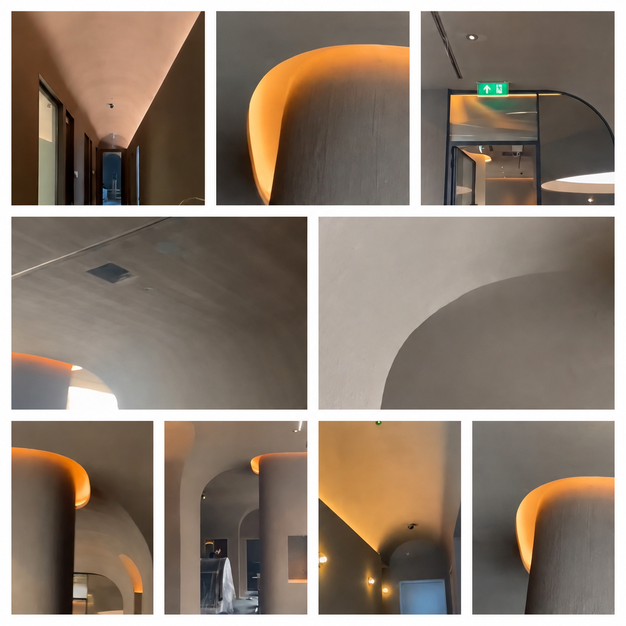
At Aspire Dental, the curved corridors included large semi-circular features. We could have made each semi-circle as one piece. However, that approach would have created a heavier component that was harder to palletise, transport and handle.
Two Sections Created a Better Site Solution
We redesigned each semi-circle as two smaller sections. As a result, we roughly halved the weight of each component. The change also simplified palletisation and gave the installation team more control while moving the sections into position.
Once installed, the two parts recreated the complete semi-circle. The geometry remained correct, while the physical components became far easier to manage.
The Final Finish Changed the Construction Method
Splitting the feature introduced one extra joint, but it did not create a genuine compromise. The finished surface received approximately 25 mm of decorative clay, which covered the joint.
Moreover, the clay ruled out what might have appeared to be an obvious material choice. GRG could create the shape, but the clay would not adhere to it correctly. Consequently, we designed the construction around the finish as well as the geometry.
This example shows why complex plasterboard details cannot be considered in isolation. Weight, access, joints and finishes all affect the right answer. Our Aspire Dental curved plasterboard case study explains how we engineered and 3D modelled the sections before manufacture.
The Same Thinking Solves Different Site Problems
Aspire Dental provides the clearest example of our design judgement. Nevertheless, the same approach works across very different plasterboard features.
Neptune Wharf: Repeating a Tight Radius
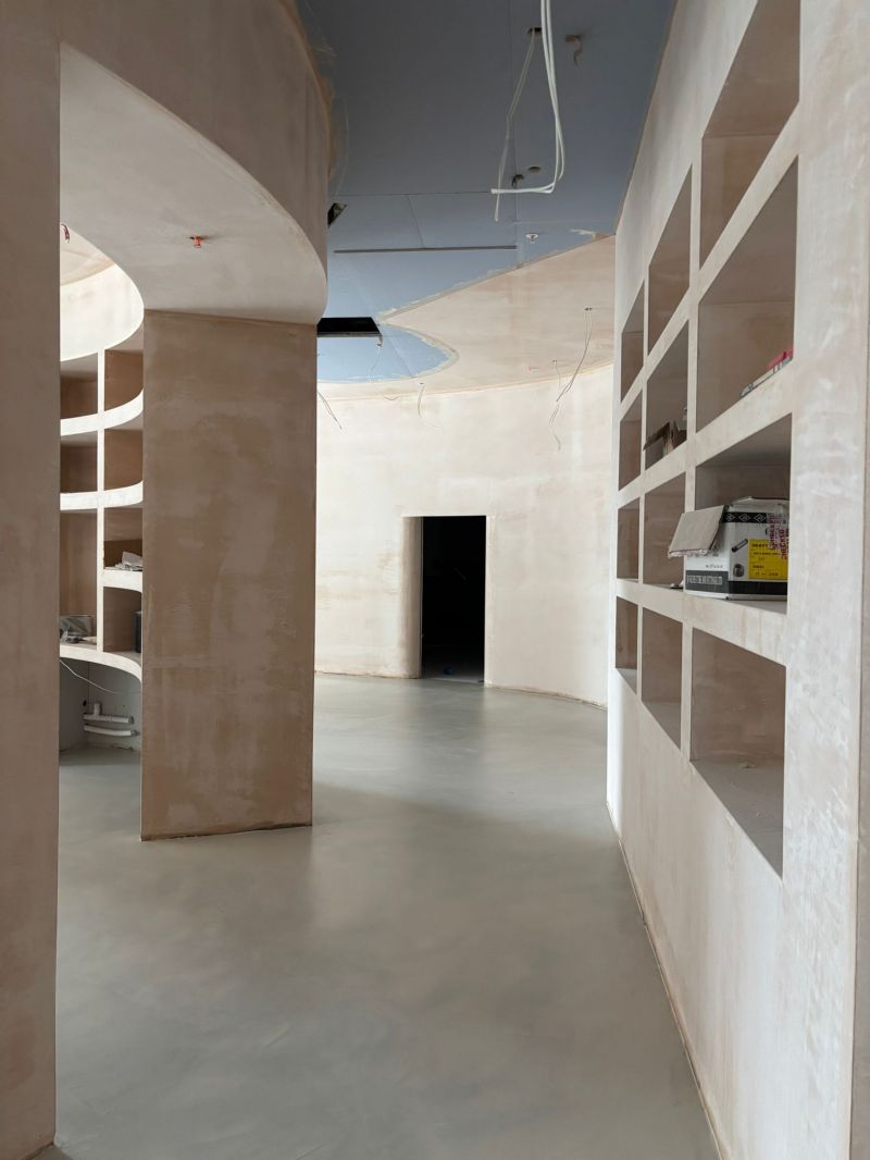
At Neptune Wharf, NewRise Drylining needed tight-radius partitions for a residents’ amenity space. Forming each curve traditionally would have required repeated setting out, templates and adjustment.
We reviewed the geometry and manufactured repeatable curved sections offsite. Therefore, the site team could focus on positioning and installing the components instead of recreating the radius each time. The Neptune Wharf case study shows how we prepared those sections for site.
Manchester Airport: Moving Ceiling Work Offsite
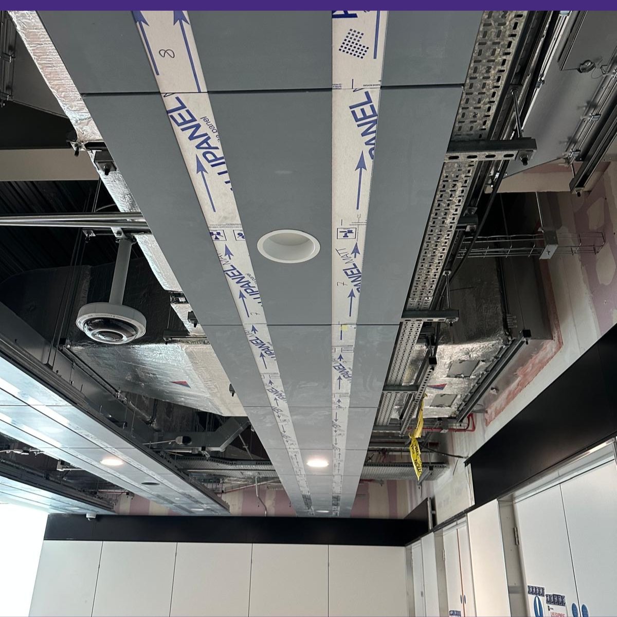
Manchester Airport required a series of large ceiling foils. Building them traditionally at ceiling level would have meant extensive cutting, forming and adjustment in a demanding environment.
We resolved the geometry and manufactured the parts under controlled workshop conditions. The original site-built approach was expected to take about 14 weeks. Moving the complex work offsite reduced that element of the programme to around three weeks. Our Manchester Airport ceiling foils case study explains the project in more detail.
Shadow Gaps: Controlling Visible Transitions
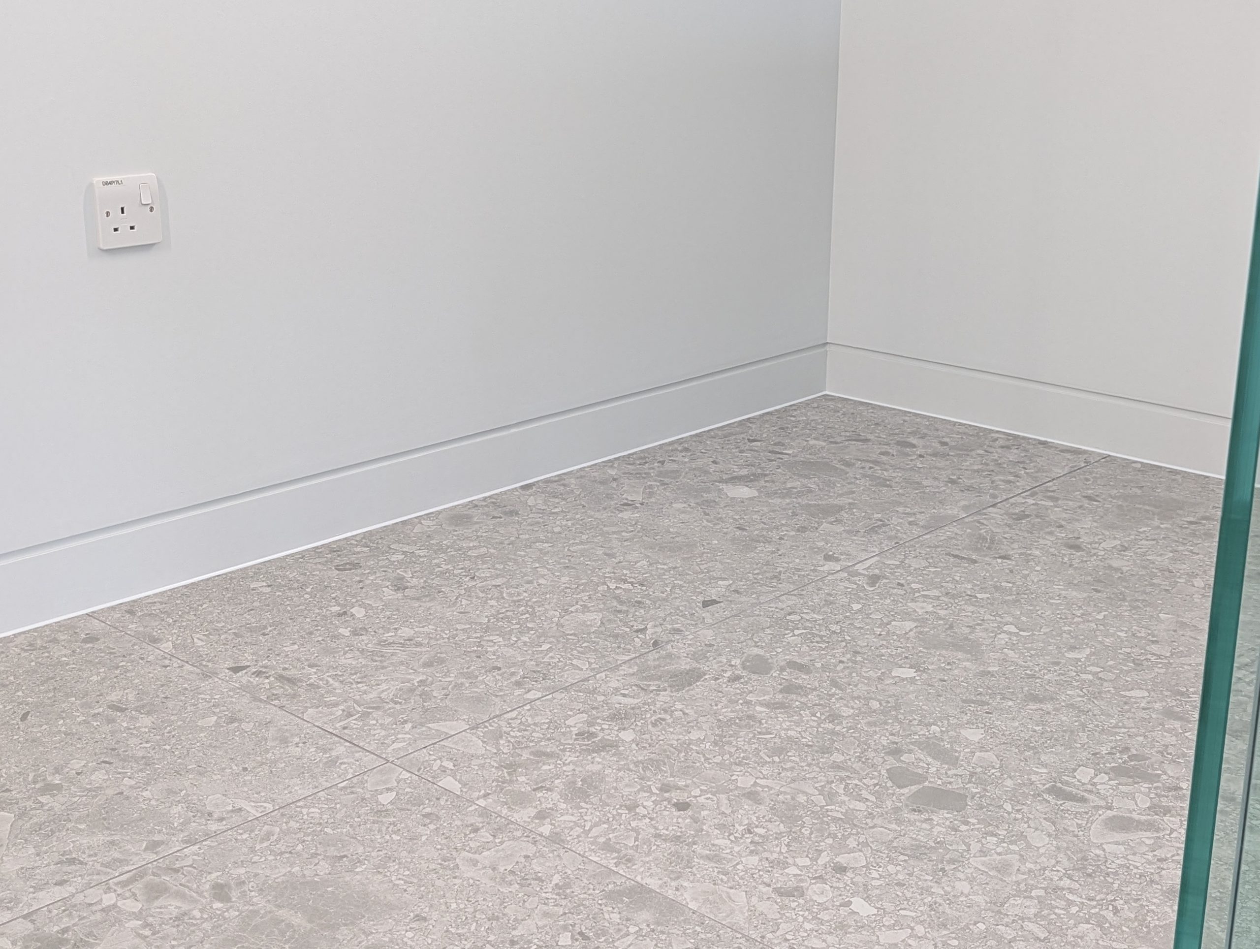
Not every difficult detail is large. A shadow gap is relatively small, but inconsistent lines and corners become obvious after decoration.
For one project, we manufactured the GRG profiles and project-specific corner details offsite. Consistent components helped the site team maintain the intended line through changes of direction. Our shadow gap installation case study shows why small interfaces still need careful thought.
How We Turn Complex Plasterboard Details into Components
Every project differs, but our practical process remains consistent.
Understand the Design and the Site
First, we review the drawings, dimensions, schedules and intended finish. Then we compare that information with site photographs, access details and the surrounding construction.
Resolve the Geometry and Interfaces
Next, we study changes in shape and the points where the feature meets other work. These transitions often hide the greatest installation risk.
Divide, Model and Agree the Solution
We break the complete feature into components that suit manufacture, pallets, transport and site handling. Where required, we produce 3D models or coordinated manufacturing drawings so the team can review the solution before production.
Manufacture for the Installation Sequence
Finally, we CNC cut, form and assemble the components in our Essex workshop. We can label and organise them by floor, area, zone or installation sequence.
The aim is not to send a collection of shapes. We deliver an organised package that makes sense when it reaches site.
Bring Us the Problem Before It Reaches Site
The best time to discuss complex plasterboard details is before the site team has to solve them at the installation point.
Send us the drawings, but also show us the surroundings. Tell us about access, lifting, adjoining work and the final finish. That information helps us design components that work in the real building, not only on the CAD screen.
You can explore our offsite plasterboard case studies to see how this approach works across architectural walls, ceilings and project-specific details. If your project includes curved plasterboard walls and ceilings, you can also view our dedicated product page.
Have a difficult plasterboard feature? Send us the detail and let us work out how to make it economical, manageable and quicker to install.
